The remote garage opener
Life is a very complex thing. In january 2009, I've decided to make it at least a little bit easier by simplifying the process of opening the garage door. Instead of "running to the gate lock, inserting the key, turning the key, removing the key, running to the car" this whole process can now be done with just one button press from inside the car.
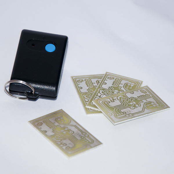
Sender
To open the gate you can use the remote control as it is shown in the picture. Inside this remote communicates a Atmel Tiny13 controller with a RMF02 wireless-module. These modules can be obtained for example from the German distributor "Pollin Elektronik". They are very cheap and suitable for self-made projects that need wireless communication. By using standby-modes of the components, a battery life of up to 5 years is estimated. As the circuit board is designed on one layer, one can easily rebuild this device on his own.
As mentioned in another article, I have modified the remote in 2011 in order to integrate it into my car. Now it is triggered by a button in the car's dashboard, looking as it was made by the manufacturer. Here's what I've changed.
Sender (automotive version)
The main difficulty while building the automotive version of the remote was the dashboard button. When pressing it, the switch does not conduct fully but has a relatively high switching resistance instead. Because of this, I couldn't just wire the new switch to the position where the original remote control switch was. I connected the dashboard button with a transistor which will then trigger a relay, which will eventually power the remote control circuit.
Despite the fact that this modification was sufficient, I decided to change even more. As the remote is connected with the car anyway, why shouldn't I use it as a power source? Because of this I dropped the coin cell and connected the circuit to the 12V power source of the car. This ensures that I do not have to disassemble everything again just because of a flat battery in the remote.
Furthermore I am using a slightly better antenna (well, almost everything is better than raw copper wire ;-)) which is hidden behind the dashboard. This improves the signal transmission and increases the working range of the remote.
At last, because of all the new parts, I decided to create a completely new PCB layout. This time I did a double- instead of a single-sided layout. Although there are more parts in the new remote, the size of the PCB is even smaller than before! I got it from 50mm x 30mm to about 47mm x 22mm. This simplifies the fitting inside the dashboard a bit.
Receiver
The receiver contains a Atmel processor and a RFM wireless-module, too. This time however I used a ATmega8 and a RFM01. As the size of the board is neglible, larger components were used on this board. Basically the device simply waits for a specific data package. Upon reciept of this package, it simulates the 'turning of the key' by shorting two wires with a relay. Nothing had to be changed on the circuitry of the motor controller itself. In fact, this device can be used everywhere you want to have a remote controlled switch.
As the garage is built out of reinforced concrete, the range is highly shortened. The remote can still be used in a range of about 10 - 15 meters, though. Without any wall in between sender and receiver, a range of 200 meters and more is possible.